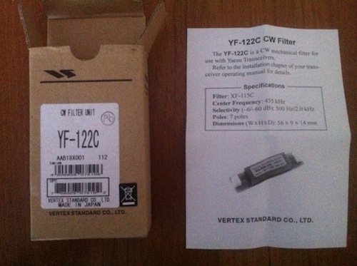
I decided to add a CW filter to my FT-817. Although I would hardly call it a mod, it still falls under the heading of “doing a modification” I guess, so I will describe it here.
A month or 2 ago I decided that it’s time to do another new thing in this nice Radio Amateur hobby we have. I decided to learn “the code”, a.k.a. CW, a.k.a. morse code!
I will write about my experiences in doing this some other time but suffice it to say that in CW mode you really need filters. Without a filter you can hear 5 (or more) different contacts going on at the same frequency at the same time. It’s very difficult to understand in the end who you’re talking to, especially for a person just starting out in morse code.
In the end I decided to get a 500Hz filter. This will remove more or less 80% of other signals as long as I tune (zero beat) right. The 300Hz filter would be a bit to narrow and would only work good in contest situations, not in the day to day CW contacts.
Putting the filter wasn’t much of a mod I must say. The people at Yaesu already made room for it in the transmitter and they did this pretty fool proof. You have to push the filter on top of a few pins; 3 on the left side and 4 on the right side which makes it pretty well impossible to do this wrong!
Anyway, as with my other mods I will show a few pictures of how it looks in a before and after situation.

The before situation. You can see at the bottom, next to the ribbon cable some open space where the filter will be placed.

A close up of the same open space where the filter will be put.

The filter is put in. As you can see there are 3 pins on the left and 4 on the right of the filter so it’s (almost) impossible to put it in the wrong way!
That’s it! It sounds simple, it looks simple and it was simple! 🙂
This article was first published on www.pa1ca.nl and is published here with permission of the author.

